Factored SF Vu 15 x 18910 28366 KN. FOOTINGS EXAMPLE 1 - Design of a continuous wall footing Determine the size and reinforcement for the continuous footing under a 12 in.

Corner Footing A New Model B Classical Model Download Scientific Diagram
Shear stress 28366 x 103.

. Ast 0605 x 350 x670. The building is assigned to Seismic. For an overview of the footing design process please refer to the blog post Spread Footings Under.
Thickness at the edge of footing. One-way shear and Punching shear. The typical strip footing you see in books has a symmetrically placed wall above the footing.
A foundation transfers the load of a structure to the earth and resists loads imposed by the earth. There is a moment of 250 kNm permanent and 200 kNm imposed. It is desired to design the footing to satisfy all requirements using the concrete grade of 30 Nmm 2 and steel of yield strength 500 Nmm.
1- Select a trial footing depth. Detailing ol the Designed Footing SAQ 2 Design and detail a trapezoidal combined footing witlz. The distance m should be greater than Zf fig411a.
Design an isolated edge footing to support an edge column 70 cm 25 cm in cross section and carries a dead load of 25 tons and a live load of 20 tons. Design of Raft Foundation Page 9 3. Figure 1 Raft layout.
Footings Example 1Design of a square spread footing of a seven-story building Design and detail a typical square spread footing of a six bay by five bay seven-story building founded on stiff soil supporting a 24 in. The bottom of the footing is 13 ft below finished grade. Any suggestions on where to look for design examplesreferences to design a footing for residential construction.
One meter edge is around the edges columns. Footing design includes two shear checks per ACI 318. Failure usually occurs on one side of the footing.
A foundation in residential construction may consist of a footing wall slab pier pile or a combination of these elements. Raft foundation has been modeled in SAFE software. Cases is an edge-loaded footing where the edge of the column is placed at the edge of the.
The plan of the raft is shown in figure 1. The structural pad foundation is to be designed against a Permanent load of 1200 kN and Imposed load of 550 kN. The shear strength is usually provided by concrete alone in order to avoid expensive shear reinforcement therefore shear could control the footing thickness.
Instructional Materials Complementing FEMA 451 Design Examples Foundation Design 14-7 Reinforced Concrete Footings. Assume - Equivalent or weighted PI 30 10 ground slope C5 Fig. 8 11 6 TSF Unconfined Co Fig.
Standard construction around here is to use a thickened slab edge or strip footing. 20 Φ RTS 2 bottom. Pad Foundation Design Example using prescriptive method.
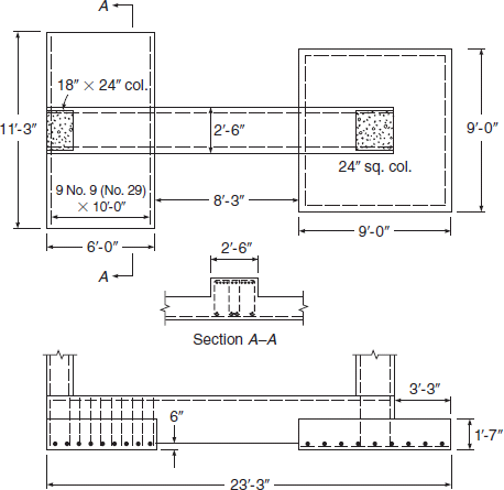
Raft Modeling and Analysis. 427m 1 a Detailing of the Trapezoidal Footing b Plan showing Longitudinal Reiforcement Figure 179. Solved example on the design of combined footing.
In some cases additional footings often a thickened slab are necessary under bearing walls or columns in the center of the. The column size is 450 x 450mm. Basic Design Criteria concentrically loaded d2 all sides c Critical section for two-way shear b Critical section for one-way shear a Critical section for flexure Outside face of concrete column or line midway between.
In contrast pile-supported foundations transmit design loads into the adjacent soil mass through pile friction end bearing or both. Two 300 x 300mm square columns spaced at a distance of 245 m cc are loaded as shown below. 16 Φ RTS top.
This course will addresses the. 100 Pt from Table 2 of Design Aid 0605. Reinforced Concrete Mechanics and Design 7th Edition 2016 James Wight Pearson Example 15-5 spMats Engineering Software Program Manual v812 StucturePoint LLC 2016 Design Data f c 3000 psi normal weight concrete f y 60000 psi Preliminary footing thickness 36 in.
9 12 PIo 30 x 11 x 12 396 Use an Effective Plasticity Index of 40 for design purposes HOUSE GEOMETRY AND LOADS It is. The major structural components of a slab-on-grade foundation are the floor slab itself and either grade beams or foundation walls with footings at the perimeter of the slab see Figures 4-2 and 4-3. Options and Concepts.
Ast 1884 mm2 1419 mm2. Sloped and stepped footings that are designed as a unit shall be constructed to assure action as a unit. 100 1419 mm2.
W 4 kft axial load due to overturning under wind loading. The foundation is founded on soil of a bearing capacity of 125 kNm 2. Bearing wall of a 10 story building founded on soil.
The raft has x side spacing of 7 meters and y-side spacing of 6 meters. The building has a 10 ft high basement. Design of Combined Footings 4m I O 8 - 8 legged str.
When footings are to be placed adjacent to existing structure as indicated in figure 411 the line from the base of the new footing to the bottom edge of the existing footing should be 45Or less with the horizontal plane. Νc 4 ksi y 60 ksi Dead Load D 25 kft Live Load L 125 kft Wind OT. Max bearing stress 200 Nmm 2.
Residential Foundation Design. Maximum Shear Force 8920 x 212 18910 KN. Fyk 500 Nmm 2.
In reinforced and plain concrete footings the thickness at edge shall be not less than 150 mm for footings on soils nor less than 300mm above the tops of files for footing on piles. Use f 250kg cm2 c f 4200kg cm2 y q gross 25kg cm2 all 17t m3 g soil and Df 15 m. Fck 40 Nmm 2.
Two examples of this failure are.

General Cases Of Square Footings A Concentric Footings B Edge Download Scientific Diagram
Complete The Design Of The Strap Footing In Example 16 4 A Chegg Com

Eccentric Footing Difference Between Concentric And Eccentric Footing Uniaxial Biaxial Eccentric Youtube

Edge Footing A New Model B Classical Model Download Scientific Diagram

Foundation Details Engineering Feed
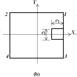
General Cases Of Square Footings A Concentric Footings B Edge Download Scientific Diagram
Design Of Boundary Combined Footings Of Rectangular Shape Using A New Model
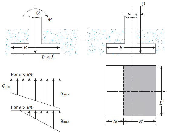
Eccentrically Loaded Foundations Structural Guide
0 comments
Post a Comment